Adapted for the web from “Modeling a Lehigh Valley GP38-2,” by Jim Six, PROTOTYPE MODELER, January 1986, p. 31, and “Modeling the Lehigh Valley GP38 & GP38-2,” MAINLINE MODELER, February 1987, p. 27 by permission of the author and copyright holder. Prototype photos by Warren Calloway. Model photography by the author.
Editor’s note: When this article was written in 1985, the Athearn GP38-2 kit had just been released, and broke new ground in the level of detail and the provision for adding more details. In 2001, when this is being edited for the web, this level of quality has been surpassed, and Jim’s opening section reviewing these advances has been omitted. However, the Athearn GP38-2 remains a good model, and still the best plastic model of this locomotive in HO. One correction needs to be made to the dynamic brake section, though. The locating holes for the dynamic brake vent should be filled in and sanded smooth, since the GP38-2 did not have this feature.
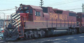
Warren Calloway photo
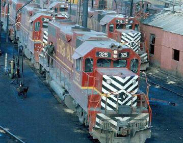
Warren Calloway photo
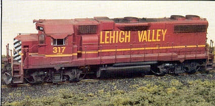
Lehigh Valley’s GP38-2
Built in November of 1972, the Lehigh Valley GP38-2’s were among the most modern power on the LV roster in the years preceding Conrail. At an even dozen, they were assigned LV numbers 314-325 with builder numbers 7387-1 to 7387-12. Though scheduled to become Conrail 8163-8174, their relative newness should have guaranteed they would never display CR’s blue paint. They did sport a blue paint job later though, but it was D&H blue. Ownership of these locomotives was transferred to the D&H as a precondition of the pending creation of Conrail. They were renumbered 7314–7325. Lehigh Valley’s four older GP38AC locomotives (LV 310–313) stayed with the road and became Conrail property as Nos. 7656–7659. Several of the 38 Dash-2’s were seen operating on the D&H several years later in LV red livery, but with D&H herald and numbers stenciled over the black diamonds of Lehigh Valley.
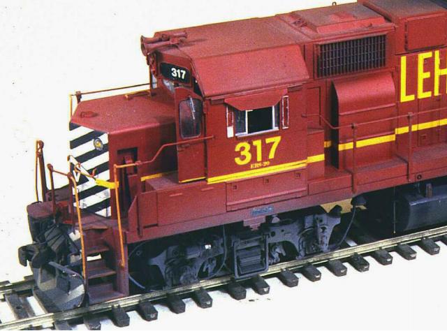
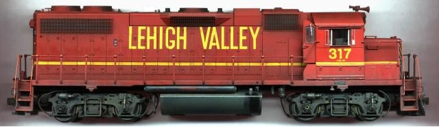
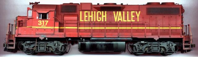
Noted for multiple but attractive paint schemes, Lehigh Valley ordered these locomotives in red with yellow-gold lettering and trim stripes, with full-front black and white safety striping. The rear of the long hood sported an LV black diamond trimmed in white.
The GP38-2 model
In an innovation that was exclusive to Athearn at the time this model was introduced, four rather substantial mounting brackets extend down from the inside of the body shell and pass through the frame at the fuel tank, locking the shell in place with the spring tension of the styrene. The result is a firm mount and no unsightly holes along the walkways. The fuel tank is short, matching the standard-size tank offered by EMD and is the proper cross-sectional shape and size. The frame itself has been designed to provide the appearance of the prototype EMD Geep frame. The visible part is recessed inward toward the center of the locomotive – as on the prototype. The frame bolsters just inside the jack pads are also the correct shape and size.
The power trucks are identical to the previously revised Athearn type B-B trucks, but the sideframes are Blomberg type-M like those on the majority of GP38-2’s. Changing them to Blomberg type-B trucks, found on Conrail, Soo and other railroads, requires only a swap of sideframes. Like the type-B’s, the Blomberg M’s have brake cylinders which are separate pieces. They must be pressed into place, along with the shock absorbers (snubbers) and truck spring hangers. Going a step further, the new sideframes have molded-on sanding pipe hangers. Overall, they are the nicest detailed trucks I’ve seen anywhere.
To superdetail most model locomotives produced before the introduction of Athearn’s GP38-2, prototype modelers not only were concerned with grabiron and lift ring locations, but also their positioning and alignment. To facilitate the work of prototype modelers, “dimples” are located everywhere a wire grab mounting hole needs to be drilled, and bolt heads are right below each. There is also a small dimple locating each position where a lift ring needs to be installed. Find the boltheads, drill holes just above each (1 use a short piece of .015″ piano wire as a drill bit; it gets too expensive breaking all those No.80 bits!), then fit Detail Associates grabirons in place. A touch of cement on the inside of the shell where the grabs are mounted will secure them.
Depending upon the particular prototype railroad you happen to be modeling, a grab here or there may have to be added or removed. In the case of adding grabs, Detail Associates provides the correct boltheads (part No.2201). To install any additional boltheads, it’s recommended to first install the grab, let the cement harden, then drill for and fit the boltheads. This eliminates the trouble associated with trying to drill two side-by-side holes (one each for the grab and bolt). Typically in this situation, while drilling the second hole the drill slides over into the first.
I began by first inspecting the undecorated body shell for flaws and found only one. Inside the shell below the battery box on the engineer’s side, a plastic nub (where a stanchion mount comes through from the outside) had to be cut away-it was preventing the shell from fitting snugly against the frame. The next step was to remove the cab (later replaced with a Cannon & Company cab). All holes for mounting grabs, lift rings and cut levers were drilled, then lift rings and some grabs were cemented in place. I say some because grabs at the hood ends were left off until after the shell had been painted and decals applied. My years of preparing such models have effectively demonstrated that decals are more easily applied before such fixtures are in place. Have you ever attempted to get a decal in place over the top of a grabiron?
I replaced the Athearn horn with a more accurate Leslie type from Details West. Should you wish to retain the Athearn cab instead of using the Cannon cab, the old mounting hole for the horn needs to be filled. A good method for this is to install the Athearn horn and secure it in place by applying cement from beneath the cab roof. Once the cement dries, cut away the horn flush with the roof top. Place a dab of ACC cement at that spot and scrape it smooth once the ACC hardens.
Only a few other detail items need to be installed on the body shell. M.U. receptacles and drop steps were attached at the walkway ends above the pilot facings. A fuel tank air filter set (Details West No.139) was fitted beneath the walkway just in front of the fuel tank on the engineer’s side, and a bell was also situated below the walkway, but aligned under the turbo blower duct on the fireman’s side of the body. ACC cement was used to secure these parts in place. Make sure they clear the frame when the chassis is installed.
The last items are two small “running lights” (Details West No.172) aligned directly beneath the cab side windows on the bottom edge of the frame side sill. These lights are used to illuminate the ties at night so the engine crew can tell whether the train is underway or if the locomotive wheels are slipping. Remember, the speedometer on these (older) locomotives was driven by turning axles, not by radar as on newer units from EMD and GE.
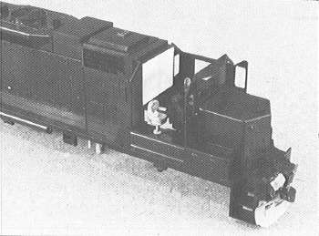
The Cannon & Company cab
The next step was to assemble and install the Cannon & Company cab (No. TC-1501). It was put together “in place” to ensure proper fit. Note as you read this, the cab roof was not installed until much later in the project. GSB wipers should be installed at this time. Another note: My model has no wipers since none were at hand or available locally as this was written. When I can get some, they will be installed. You will need to drill and fit the wipers above all front and rear cab windows. It’s almost impossible to do this with the cab in place without damaging the model with the drill. A strand removed from 22-gauge stranded wire can be used for the cross connector between the wipers on the two center windshields.
The Cannon cab is an extremely nice model in itself in that the window frames, cab doors, rain gutters and sunshade brackets are separate parts and can be positioned to suit the individual modeler. The cab walls are sufficiently thin to eliminate the thick look always being criticized by brass fanciers. I left open both the front and back cab doors and mounted the sunshades slightly offset in the channels to enhance the “having been used” appearance. The windows on the engineer’s side were fitted partially open for the same reason. The sunshades were cut from sheet styrene (.005″ to .010″ thick), since commercial sunshades have representations of the attached channel and cannot be used in the Cannon channel. To maximize the effect of the open cab doors, seating for the crew was installed and an engineer’s control panel was cemented in position. Sheet styrene was attached to both the front and back sides of the cab interior covering the openings into the hoods. These panels were cut short enough to clear the drive mechanism.
Another nice feature of this cab is the recessed louver vent below the engineer’s window on the cab face. The Athearn cab does not have this feature, nor does it have the rivets on the panels flanking the cab side windows. A Leslie RSL-3L-R air horn (Details West No.190) was fitted to the roof section above the number boards when the cab was in place but with the roof still off. Cab window wind deflectors from Detail Associates were cemented to the sides of the cab adjacent to each side window. These will be painted silver when the model is near completion.
Before cementing the cab roof in position, the inside of the cab was sprayed with a coat of Floquil’s Erie-Lackawanna Gray and the seat cushions were brushed flat black. At this point, the entire body was painted red, being careful not to cover the gray cab interior. To duplicate Lehigh Valley red, I used a mixture of 50 percent Accupaint Cornell Red, 25 percent Floquil Signal Red and 25 percent Floquil Caboose Red. The paint was then diluted half-and-half with lacquer thinner. Allow sufficient time for the paint to dry-this can be determined when most of the paint odor is no longer present.
Fit the cab window glass at this time, and carefully follow the instructions and window patterns provided with the Cannon & Company kit. The glass neatly fits into tracks around the inside perimeter of the window openings, further adding to the “thin” appearance of the cab walls. Be careful not to get spray on the windows while weathering the model. If you do, a small but stiff paint brush and Walthers’ decal setting solution will clean it off. Carefully install the cab roof at this time.
The chassis
Attention should now be directed toward the chassis. If you’re into repowering your Athearn locomotives with Proto Power West motors and flywheels (or those of another brand), now is the time to do so. Proto Power offers this very chassis in ready-to-run form, already equipped with their popular can motor/flywheel combination. However, for the sake of those modelers preferring to retain the stock Athearn mechanism, this model was done without repowering the unit. If this is your choice, first remove the long, stamped-metal clip that is used to transmit electrical power from the trucks to the motor. Solder wire in its place.
Install the couplers, being sure to check the coupler height. I chose to utilize the diesel coupler pocket from Overland Models (part No.8000). The instructions provided with the pockets state that a Kadee No.5 coupler should be used. But, sticking to my preference for the older style No.4 coupler, I filed its sides, top and bottom smooth (it’s too large otherwise) and carefully se- cured it in position with ACC cement. When “body mounting” the couplers with the Overland pocket, part of the cast-on coupler mount at each end of the frame has to be removed in order to clear the draft gear attached to the pilots. The frame was clamped in a vise and a fine-tooth hacksaw made quick work of it.
The fuel tank needs only minor detail work to bring it to the level of the rest of the effort thus far put into the locomotive. The seams along the sides of the tank were filed smooth and the protrusions just in front of the tank gauges were removed. I used an auger bit in my Dremel tool to do this. A crankcase drain pipe was fitted to the front of the fuel tank on the fireman’s side of the chassis by drilling and mounting Detail Associates metal eyebolts and passing a. 020″ piece of brass wire through them. (See the photos.) All was then secured with ACC. Precision Scale Company fuel filler pipes (part No.39080) were installed. The filler pipes were fitted by first drilling .030″ holes approximately 3/16″ to 1/8″ in depth and angled in the direction the pipes would be positioned. The pipes were then cemented in place with ACC.
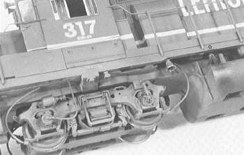
With its empty space below the frame (between the fuel tanks and trucks) and mounting brackets already on the truck sideframes, this model begs to have sand pipes fitted. I’ve been applying sand pipes to my locomotives for several years now, but on no other model has this proven so effective, or so simple. For the “flexible” sand pipes themselves, wire removed from scrap grain-of-wheat bulbs (or wire of comparable size) was utilized. It’s pliable enough to permit the trucks to swing freely, yet at the same time sufficiently resilient to retain its shape. The wire was cut long enough to reach from the bracket at the ends of the truck sideframes, and then curve gently up and along the underside of the frame. In this way the pipes remain free at one end (the top), and still retain a prototypical position when the locomotive is in operation. The wire fits snugly into the pipe hangers on the trucks – it’s as though they were designed that way, and maybe it was. A dab of ACC ensures they’ll not pop out during operation.
The last major step in preparing the Athearn GP38-2 is the installation of stanchions and railings. Preformed wire is provided for railings, but this wire is unprototypically thick (.025″- .030″) – especially when a few coats of paint are applied. I used .015″ piano wire, but if you have .017″ or .018″ wire available, use it. All railings should be measured and then bent to shape using a relatively small pair of needle-nose pliers. Next, slip the stanchions over the railing wire and tap the assemblies into place. After carefully aligning everything, apply a dab of ACC to ensure each joint remains securely in place. Carefully spray or brush the railing assemblies with the same red used on the body. The end sections of the railings are brush painted SP Daylight Red (really a deep orange), as were all grabs.
The locomotive was then given its last, but most important detail, weathering. Mix your weathering colors to match that found on locomotives frequenting your setting and use them thin – 80 percent or more lacquer thinner. In this way the effects of the weathering agents can be built up gradually to suit your tastes.
Closing notes
Like past layouts, my model locomotives never seem complete. There’s almost always something I’d like to add or change as new products and new model technologies become available. As I write this text describing the completion of LV No.317, there remain things yet to be done to the unit. Among the obvious are the windshield wipers, headlight lens and front m.u. receptacle. Did you notice them missing in the photographs? All are on order and haven’t yet arrived. I’d also like to put glass in the sight window located in a door on the engineer’s side of the long hood. I haven’t decided how to accomplish this in a way I’m willing to apply to several other models. Another thing I’d like to do differently (on future models) is to install handrail stanchions of the proper cross section. The new Athearn parts are an improvement, at least in ease of installation, but aren’t at the level of prototype accuracy on the rest of the model. A few commercial offerings are available, but most lack a mounting pin (necessary if the locomotive is to be anything other than a shelf display). The sets from Precision Investment Associates are quite nice and have mounting pins. I am fitting a set to an SD40-2 now in the works and am quite impressed.

BILL OF MATERIALS |
|||||||||
| Key | Description | Manufacturer | Part No. | Key | Description | Manufacturer | Part No. | ||
| 1 | air filter set | Details West | 139 | 14 | handrail, brass | Detail Associates | 2205 | ||
| 2 | bell | Detail Associates | 1202 | 15 | Leslie horn | Details West | 190 | ||
| 3 | cab sunshade | Detail.Associates | 1301 | 16 | m.u. hoses | Detail Associates | 1508 | ||
| 3 | cab sunshade | Precision Scale | 39048 | 16 | m.u. hoses | Precision Scale | 3153 | ||
| 4 | cab wind deflectors | Detail Associates | 2304 | 17 | m.u. stand | Detail Associates | 1505 | ||
| 5 | cab, Dash-2 type | Cannon & Company | TC-1501 | 18 | running lights | Details West | 172 | ||
| 6 | couplers | Kadee | No. 4 | 18 | running lights, brass | Precision Scale | 39071 | ||
| 7 | curved cabocse grabiron | Detail Associates | 6503 | 18 | running lights, plastic | Precision Scale | 39072 | ||
| 8 | Dash-2 drop steps | Detail Associates | 1404 | !9 | seat, engineer’s | Precision Scale | 39091 | ||
| 9 | diesel coupler pocket | Overland Models | 8000 | 20 | seat, fireman’s | Overland Models | 8005 | ||
| 10 | eyebolts, formed wire | Detail Associates | 2206 | 21 | snowplow | Details West | 120 | ||
| 11 | fuel filler | Details West | 166 | 22 | speed recorder drive | Detail Associates | 2807 | ||
| 11 | fuel filler, brass | Precision Scale | 39079 | 23 | truck sand pipes | Walthers | |||
| 11 | fuel filler, plastic | Precision Scale | 39080 | 24 | windshield wipers, brass | Precision Scale | 3967 | ||
| 12 | fuel tank gauge | Precision Scale | 24 | windshield wipers, plastic | GSB | 3405 | |||
| 13 | grabirons | Detail Associates | 2202 | 24 | windshield wipers, plastic | Precision Scale | 3968 | ||